Capsule enclosure selection
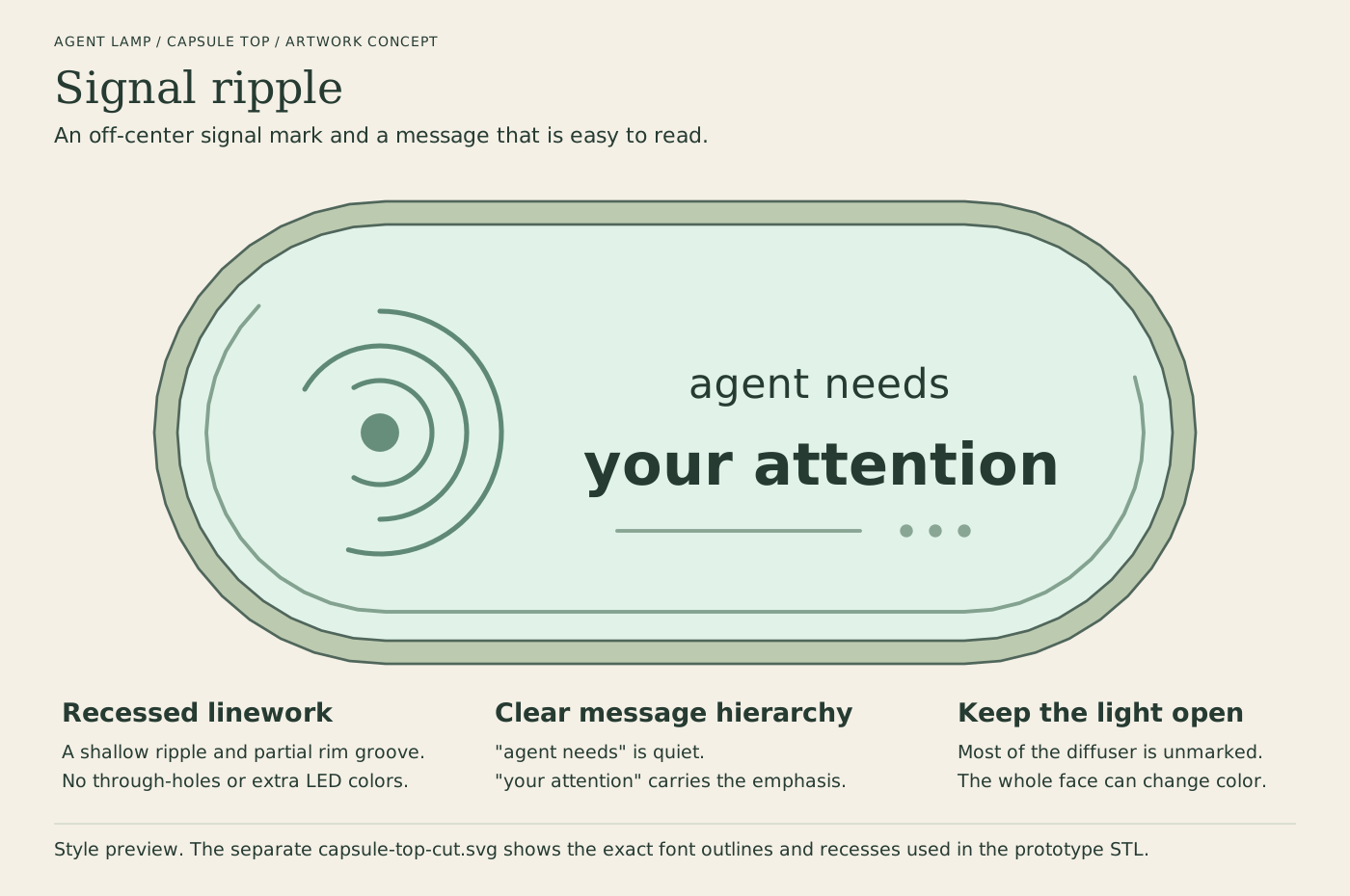
You selected the capsule cassette, with the exact top text agent needs your attention. The lettering is arranged over two lines for readability:
agent needs
your attention
The selected capsule now has adjustable prototype STL files in the capsule build guide. The model has the requested text, ripple recesses, a separate LED deck and a retained electronics cassette. Physical hardware fit remains unverified. The other three shapes remain concepts, and the older rectangular 3MF remains a legacy prototype.
Creative top: signal ripple
Open the top artwork at full size.
The left-side ripple is an original signal mark, not a logo from another project. The first line is quieter; your attention gets the emphasis. A partial perimeter groove and small waiting dots give the top some detail without covering the illuminated area.
The artwork uses shallow, monochrome recessing rather than holes or permanently colored inserts. The source-specific WLED color can still fill the whole face. The prototype diffuser STL includes the lettering and ripple cuts, with a 2 mm roof and 0.5 mm recess depth. The preview above is the style drawing; the generated cut view shows the actual IBM Plex Sans outlines used in the STL.

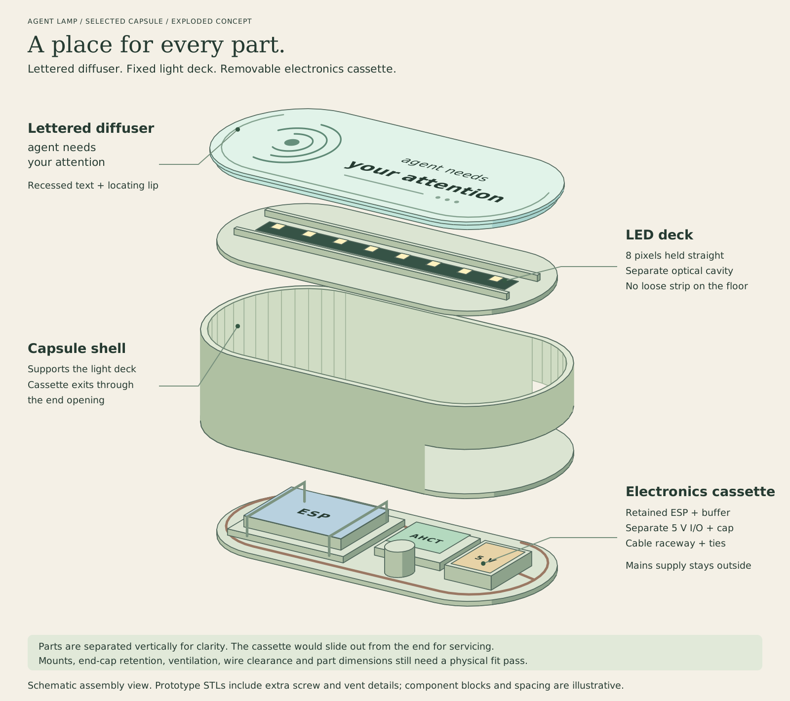
Selected capsule, exploded
Open the exploded capsule at full size.
The parts are separated vertically to show what belongs where. The electronics cassette slides through an end opening, with a retained service loop connecting it to the fixed light deck. The component blocks show mounting zones, not measured outlines of your hardware. The STL has four lid fasteners, two cassette-retaining fasteners, ventilation and tie slots that are not all drawn here. A physical fit pass is still required.
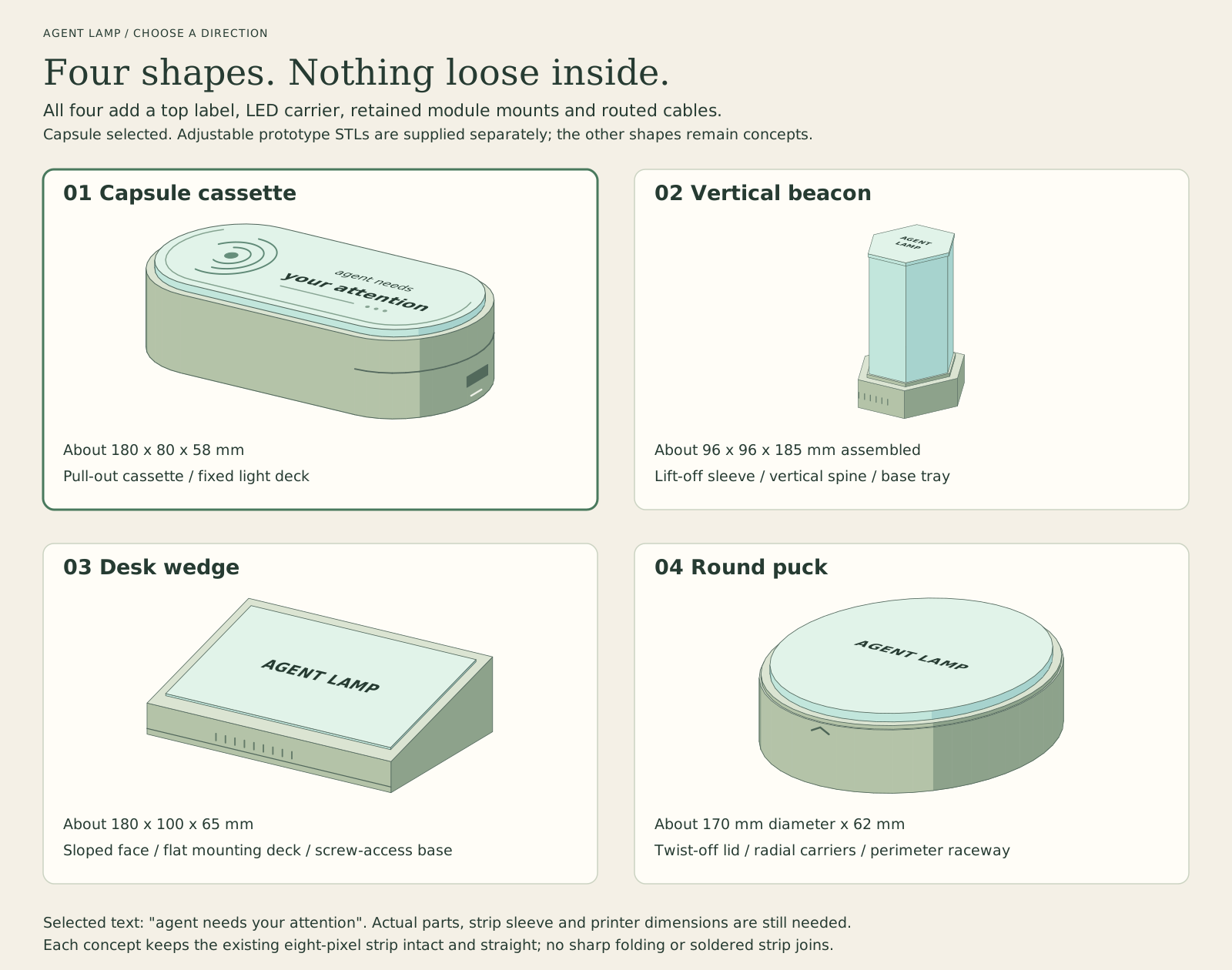
The four approaches
Open the comparison at full size.
| Option | Container and access | Internal organization | Main tradeoff |
|---|---|---|---|
| 1. Capsule cassette | Rounded, low horizontal shell; electronics cassette pulls out from an end | Fixed upper LED rail; separate retained ESP, buffer and power/capacitor carriers below | A service loop must stay captured and not snag as the cassette moves |
| 2. Vertical beacon | Faceted column; diffuser sleeve lifts off | Straight vertical LED spine above a removable electronics base tray | Small footprint, but stability and all-around light distribution need a prototype |
| 3. Desk wedge | Sloped light face; flat base opens with four captive-nut screws | Broad slotted mounting deck, separate sloped LED/lens deck, perimeter cable route | Takes more desk space, but offers the least cramped component layout |
| 4. Round puck | Low round enclosure; quarter-turn lid | Removable radial carrier deck, straight upper LED bridge and perimeter cable raceway | Bayonet fit and edge-to-center diffusion need tuning |
The capsule's fixed light deck and removable electronics cassette are the selected approach. This keeps the strip supported while the modules can be serviced without dismantling the light chamber.
What all four add
The selected top diffuser says agent needs your attention. The prototype uses a 2 mm roof with lettering recessed 0.5 mm, leaving 1.5 mm below the cuts. The dark letters in these illustrations represent the engraving or optional paint fill; same-material engraving would be subtler. This avoids requiring a multi-material printer. The other concepts still show the earlier placeholder label.
The inside is divided into a light deck and an equipment bay. The strip gets a straight carrier with sleeve clearance and end retention, rather than sitting loose on the floor. The controller, preassembled AHCT buffer and protected low-voltage power/capacitor modules each get a removable carrier. Slotted mounting points or straps retain those carriers without pressing on exposed components. Board-specific clips or standoffs wait until the actual board and carrier dimensions are known.
Cables run in a defined raceway with tie points. The factory strip pigtail stays intact, the service loop is retained, and a removable cable saddle provides strain relief at the entry. The USB and external 5 V entries remain distinct. The electrical grounding and backfeed precautions in the wiring guide still apply.
Only low-voltage modules belong inside the capsule. The enclosed mains-to-5 V supply stays outside. This changes the original prototype, whose electronics were external. The capsule STL adds mounting zones and ventilation, but the actual hardware still needs service-space, insulation and temperature checks.
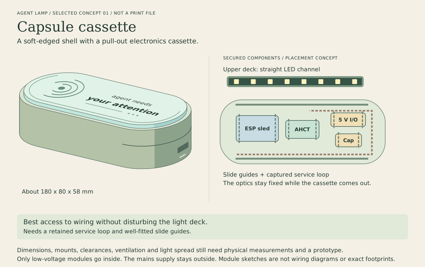
1. Capsule cassette
Open the capsule concept at full size.
Draft envelope about 180 x 80 x 58 mm. A curved end cap belongs to the removable electronics cassette. The diffuser and LED deck stay on the shell, so maintenance does not disturb the light assembly. Replaceable slide guides are preferable to assuming a perfect printer tolerance. The wiring needs a measured, captured service loop and a stop so pulling the cassette cannot strain a connector.
2. Vertical beacon
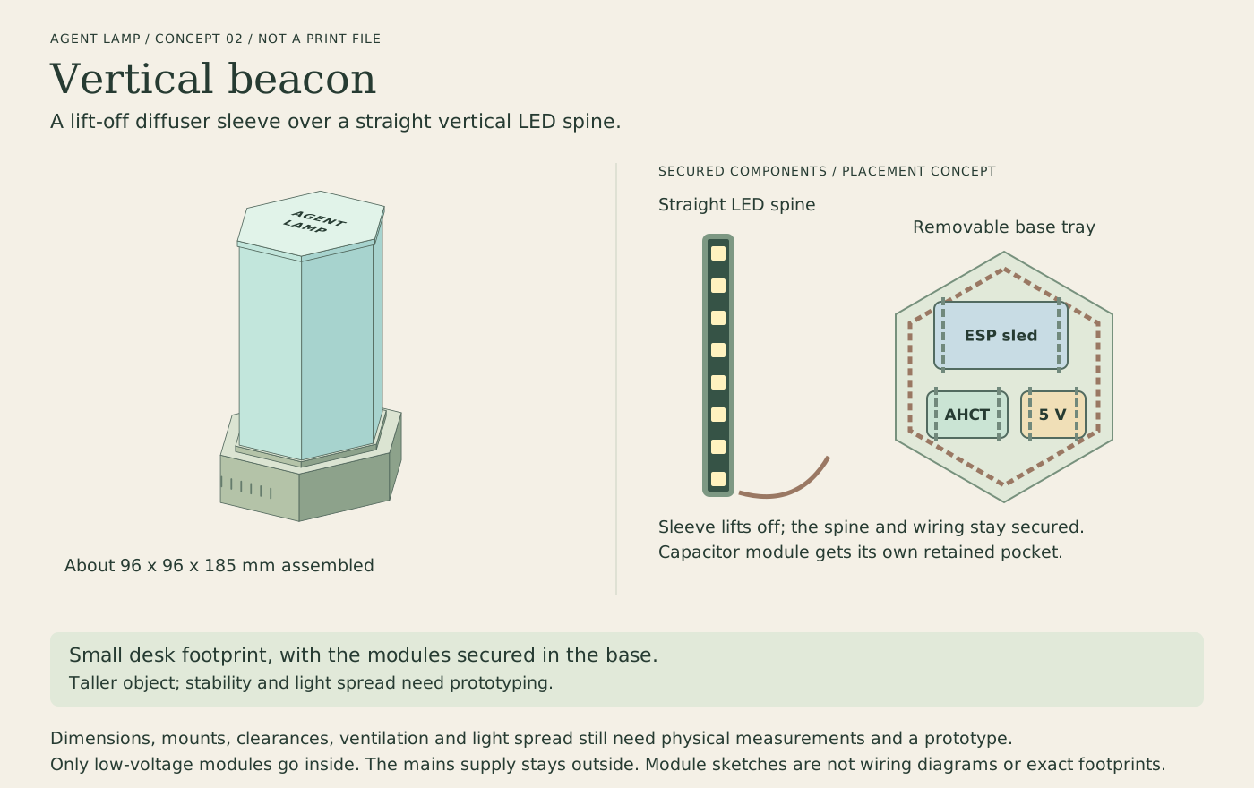
Open the beacon concept at full size.
Draft envelope about 96 x 96 x 185 mm assembled. The existing eight-pixel section runs vertically on a spine; it is not folded or cut into shorter sections. The sleeve and base would print as separate parts. The base needs anti-slip feet and a stable mass distribution. A single strip does not guarantee uniform light around every face, so the reflector and diffuser need an optical trial.
3. Desk wedge
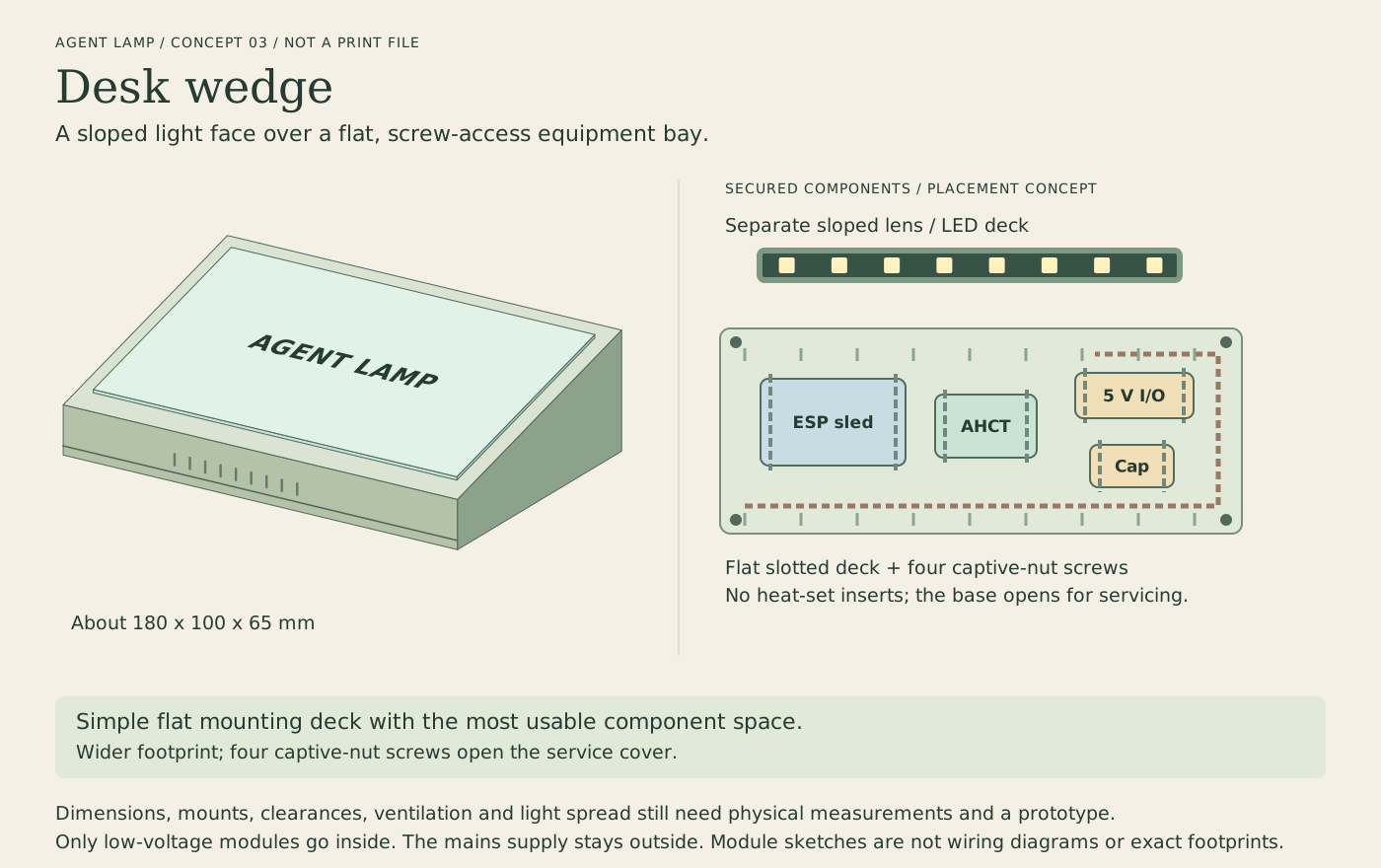
Open the wedge concept at full size.
Draft envelope about 180 x 100 x 65 mm. The light face angles toward someone sitting at the desk. A flat base holds the modules on a slotted deck, while the LED/lens assembly is a separate part. Four underside screws and captive nuts provide access without heat-set inserts. The low front edge reduces usable internal height, so the larger carrier and terminals belong toward the taller rear.
4. Round puck
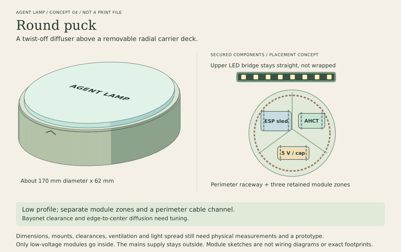
Open the puck concept at full size.
Draft envelope about 170 mm diameter x 62 mm. The lid releases with a quarter-turn motion. The carrier deck lifts out separately, so twisting the lid does not twist the wiring. The eight-pixel strip remains straight across an upper bridge; it is not wrapped into a ring. This means the circular light face needs a real diffusion trial rather than assuming even illumination.
Prototype limits
The capsule and wording are selected, and STL output is now allowed. The first model therefore uses adjustable tie slots and mounting zones instead of guessed board-specific mounting holes. Confirm the ESP and carrier dimensions, buffer/capacitor/terminal module sizes, sleeve dimensions, connectors and printer volume before treating it as a fitted enclosure.
The illustrations and STL files do not claim hardware fit, latch strength, temperature safety or printer compatibility. See the current STL build guide for support requirements, print orientation, bolt sizes, rigid-part clearance checks and remaining physical checks.
The illustrations are generated from maintained TypeScript source:
npm run design:options