Capsule build and STL files
The selected capsule now has four STL parts, with the exact wording agent needs your attention and the recessed signal-ripple artwork in the diffuser. The electronics fit a removable, organized cassette below a separate LED deck.
This is an adjustable fit-check prototype, not a confirmed fit for your actual board, carrier, sleeve or wiring. Only low-voltage components belong inside. The enclosed mains-to-5 V supply stays outside. No physical print, temperature test or loaded-wire service test has been performed.
Animated 3D view
Run npm run preview from the project folder, then open http://127.0.0.1:43822. The Three.js viewer uses these actual STL files and their assembly transforms, with play/pause, an exploded-view slider, orbit controls, a top view and part isolation. Choose Electronics to see representative modules and functional cable routes, or open http://127.0.0.1:43822/?electronics=1 directly. The example electronics are not printed parts or verified pinouts; the harness disconnects for the exploded animation. Displayed light and paint fill are simulations, and no device is controlled.
Top and exploded view
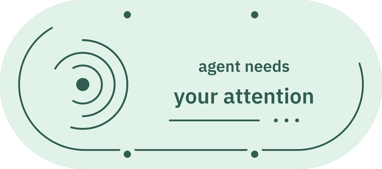
The generated top uses IBM Plex Sans outlines, recessed 0.5 mm into a 2 mm roof, leaving 1.5 mm below the lettering. The ripple, partial border and waiting dots are also recesses, not through-holes. The whole diffuser can still show the source's WLED color. Dark areas in the illustration represent the cuts; optional paint fill would make them more visible when unlit.
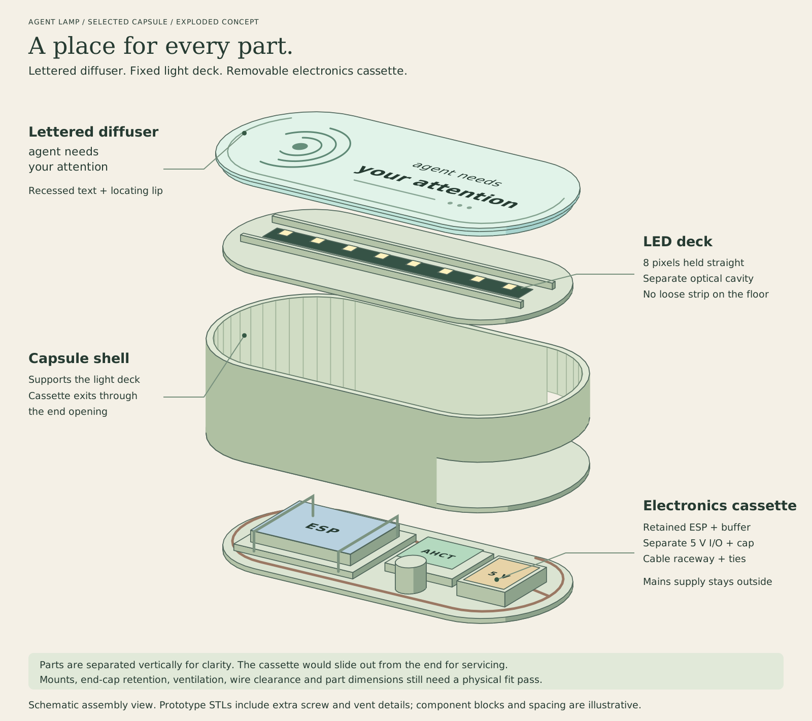
This exploded diagram explains the arrangement, not every screw post or cable slot in the STLs. The actual shell has ventilation slots, four lid posts and a supported LED-deck ledge. Two base bolts retain the cassette; the lid's retaining columns hold the light deck in place. The capacitor and boards shown in the diagram are illustrations, not printed parts.
Files and print orientation
STL files do not encode units. Import these coordinates as millimeters, keep the objects separate, and arrange them across as many plates as your printer needs. They are already positioned on their individual print beds. Do not merge them into one overlapping object or print the exploded arrangement.
| Part | File | Bounding size, mm | Orientation |
|---|---|---|---|
| Shell | capsule-shell.stl | 180 x 80 x 56 | Floor down. Supports are required beneath the cassette doorway and internal ledges. |
| Cassette | capsule-cassette.stl | 174 x 80 x 27.6 | Flat underside down. |
| LED deck | capsule-led-deck.stl | 172.8 x 72.8 x 6.4 | Flat underside down, channel facing up. |
| Diffuser | capsule-diffuser.stl | 180 x 80 x 21.6 | Lettered outer face down, lip and retaining columns facing up. Flip after printing. |
The assembled case is approximately 180 x 80 x 58 mm, excluding screw heads and feet. The diffuser's 21.6 mm print height includes its retaining columns, not a 21.6 mm thick light surface.
Use plain, nonconductive opaque PETG for structural parts and natural/translucent PETG for the diffuser. Avoid conductive carbon-filled material around the electronics. A 0.4 mm nozzle and 0.16-0.2 mm layers are starting points, not tested profiles. Check text detail and support removal in your slicer. The diffuser's text faces the bed in the supplied orientation, so it may look mirrored from above in the slicer. Do not mirror the model; flip the physical part to assemble it.
The doorway is a real overhang, not a support-free bridge. Enable suitable supports beneath it and the internal shelves, then inspect the sliced preview. Remove every support fragment before fitting the cassette. The largest parts need more than a 180 mm bed dimension once brim, keep-outs and placement margins are included.
Open the parts in Bambu Studio from the project terminal:
npm run print:open
Or export the print-only kit without opening an app:
npm run print:export
npm run print:export -- --output-dir "$HOME/Downloads/Agent-Lamp"
The kit has the four STLs, manifest, this guide and illustrations. It has no application code, secrets, printer presets or G-code. The older rectangular agent-lamp.3mf remains in the developer project as a legacy prototype; it is not the capsule.
Securing the inside
The cassette has separate controller, buffer and low-voltage I/O areas, raised dividers, repeated 3.6 x 11 mm mounting slots and perimeter tie points. Use those slots to retain preassembled carriers with thin cable ties or hook-and-loop straps. Do not tighten a strap onto exposed components or put a bare PCB against screw hardware. Use an insulating carrier/padding appropriate to your actual board.
Keep the complete module stack below about 24 mm above the cassette floor, including carrier, connectors and wires. This is a space limit, not a claim that your hardware fits. The board's antenna also needs appropriate clearance. Route the service loop through the perimeter channel and retain it so withdrawing the cassette cannot tug the LED input. The virtual fit checks cover rigid printed parts, not real wires or connectors.
The end cap has two open-top lead notches and nearby tie slots. Lay prewired leads in from above while the cassette is out, rather than removing factory connectors. Keep USB and strip-supply entries distinct, protect the edges, and add strain relief. Choose leads that fit the opening with room for insulation and gentle bends. Do not use the case as the only restraint for an external cable.
The LED channel is 144 mm long and 18 mm wide. It is intended for a straight eight-pixel section at 60 pixels/m. A sleeve no wider than about 16 mm leaves nominal side clearance; measure the actual sleeve, boot and cut length first. Keep the factory input lead intact. Orient that input toward a deck pass-through and do not crease the flexible PCB.
Hardware and assembly
Use four M3 lid bolts, two M3 cassette bolts, and six standard M3 hex nuts. The default nut pockets are 5.8 mm across flats and 3 mm deep. Typical starting lengths are M3 x 8 mm for the lid and M3 x 10 mm for the cassette, but check your nut dimensions, screw heads and engagement before use. Do not force the screws, over-tighten the diffuser or leave exposed metal able to contact circuitry.
Add non-slip feet thick enough to clear the underside bolt heads. Use thin ties/straps compatible with the slots; under-cassette clearance is about 1.8 mm. Keep tie heads above the tray, not between the tray and shell floor. No heat-set inserts or electrical soldering are required by the printed design, but the ESP headers and electrical modules must already be assembled.
- Print and remove supports. With no electronics or power connected, dry-fit the four parts and M3 hardware. Confirm the cassette slides without force, the deck sits flat, and the lid columns clear the posts. Adjust the parameters or reprint if there is interference.
- Fit the cassette nuts, retained module carriers and insulated wiring. Keep every component and lead below the LED deck and outside the slide guides. Leave a captured service loop, not loose wire that can catch on the ledge.
- Mount the short strip in its LED channel. Feed only the flexible input lead through the deck opening. Secure the strip using its appropriate adhesive or gentle retention at non-LED gaps; do not clamp an LED package.
- Configure WLED with the ESP disconnected from the strip/buffer harness. Use the board-specific firmware instructions, eight pixels, the verified GPIO, one segment with ID 0, and a conservative current limit. Unplug USB again before reconnecting the harness.
- Inspect wiring and polarity while unplugged. Fit the deck over the four posts. Insert the cassette while watching the service loop, then secure its two base bolts. Do not use the bolts to pull a jammed cassette into place.
- Perform an attended low-brightness test with the lid accessible. Check connectors, board, buffer, strip and plastic for abnormal heating or unstable behavior. Disconnect immediately if anything is wrong. Fit the four lid bolts only after the assembly is satisfactory, without trapping wires. Check temperature again with the lid fitted.
No-solder wiring and power limits
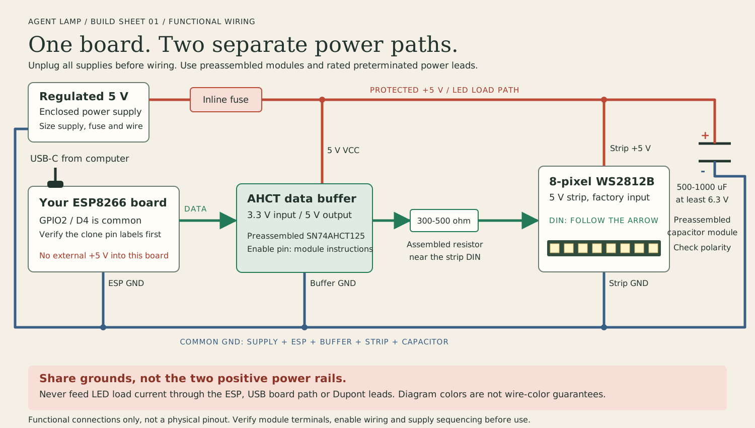
This is a functional map, not the pinout of your clone or preassembled module. Prefer your existing ESP if its headers are already soldered. Use a preassembled SN74AHCT125-class buffer or a controller with equivalent level shifting; a generic bidirectional I2C shifter is not a substitute. Use a preassembled 300-500 ohm series resistor near DIN and an insulated 500-1000 uF capacitor module rated at least 6.3 V, with correct polarity.
Use a regulated 5 V supply, suitable wiring, rated preterminated connectors and appropriate branch protection. Keep LED load current out of the ESP board, its USB path, breadboards and Dupont contacts. The conservative full-white planning bound is 60 mA/pixel, or 0.48 A for eight pixels; it is not a measurement of your strip.
Share ground between ESP, buffer, strip and strip supply. Do not connect the separately powered strip's positive rail to the USB-powered ESP's 5 V pin, and never apply 5 V to GPIO. Follow the buffer's enable and power-sequencing instructions to avoid phantom powering. Match actual connector pin order and 5V/GND/DIN labels; wire colors and matching plug shapes are not proof of polarity.
Keep the factory strip input pigtail. Cut the short segment only at the marked line while all power is disconnected and insulate the new cut end. If using a solderless clip, match the PCB width, pad layout and sleeve type; an IP67 sleeve is not interchangeable with a bare-strip connector.
Ventilation slots, low brightness and WLED software limits do not establish electrical or thermal safety. Printed plastic is not a certified electrical enclosure or fire barrier. Do not place mains wiring inside or leave the first powered trials unattended.
Source and limits
The maintained CAD source is TypeScript in scripts/capsule-model.ts; dimensions and text are in cad/capsule-parameters.json. It uses Manifold solid operations and IBM Plex Sans font outlines. The font comes from Fontsource under the SIL Open Font License; the print kit contains generated shapes, not a redistributed font file.
npm run cad:capsule
The generator checks positive, connected solids, pairwise assembly intersections, and rigid cassette withdrawal at several positions. The saved STLs are also checked for closed/manifold topology and can be passed through Bambu Studio's isolated importer. These checks do not replace a physical fit, cable-clearance, support-removal or temperature trial. No printer-specific slicing profile is included.